In this tutorial, learn how to install a low voltage transformer for landscape lighting. We’ll use a 300W multi-tap transformer, but the installation would be effectively the same for VOLT® 600W, 900W or 1200W transformers.
Supplies
- Low voltage transformer
- 0.5-inch PVC conduit
- Terminal adapter with 0.5-inch terminal ring clamp
- Box of masonry anchors and screws
- Colored tape (optional: for organizing system layout when running multiple cables)
Tools
- Needle-nose pliers
- Large flathead screwdriver
- Offset flathead screwdriver (small bit size)
- Phillips screwdriver
- Marking pencil
- Tape measure
- Pipe saw or PVC pipe cutters
- Offset wire cutters
- Wire strippers
- Hammer drill (check masonry anchors to ensure you have the proper size drill bit)
Step-by-Step Instructions
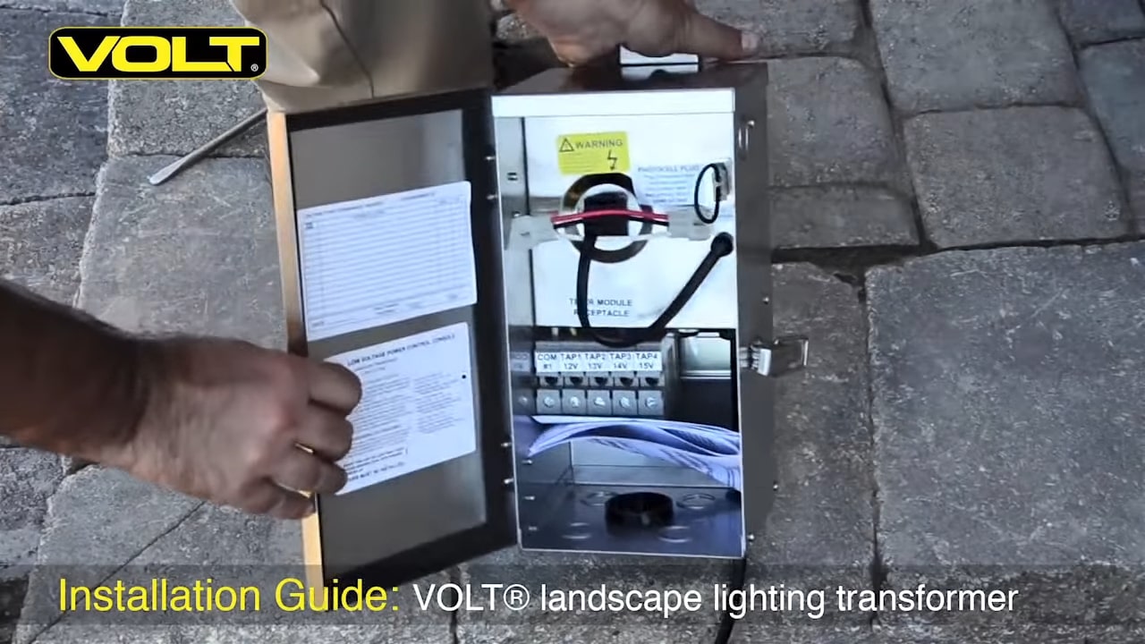
Step 1: Unbox the transformer, open the door and remove it from its hinges.
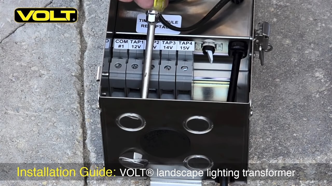
Step 2: This VOLT® transformer comes with three different sizes of knockouts on the bottom – 0.5 inch, 0.75 inch and 1.5 inch. Remove one of the 0.5-inch knockouts so that you can place wire up inside the transformer. To do this, place the edge of a screwdriver on the outer edge of the 0.5-inch ring and give it a good solid blow. Repeat this step until the plug is removed.
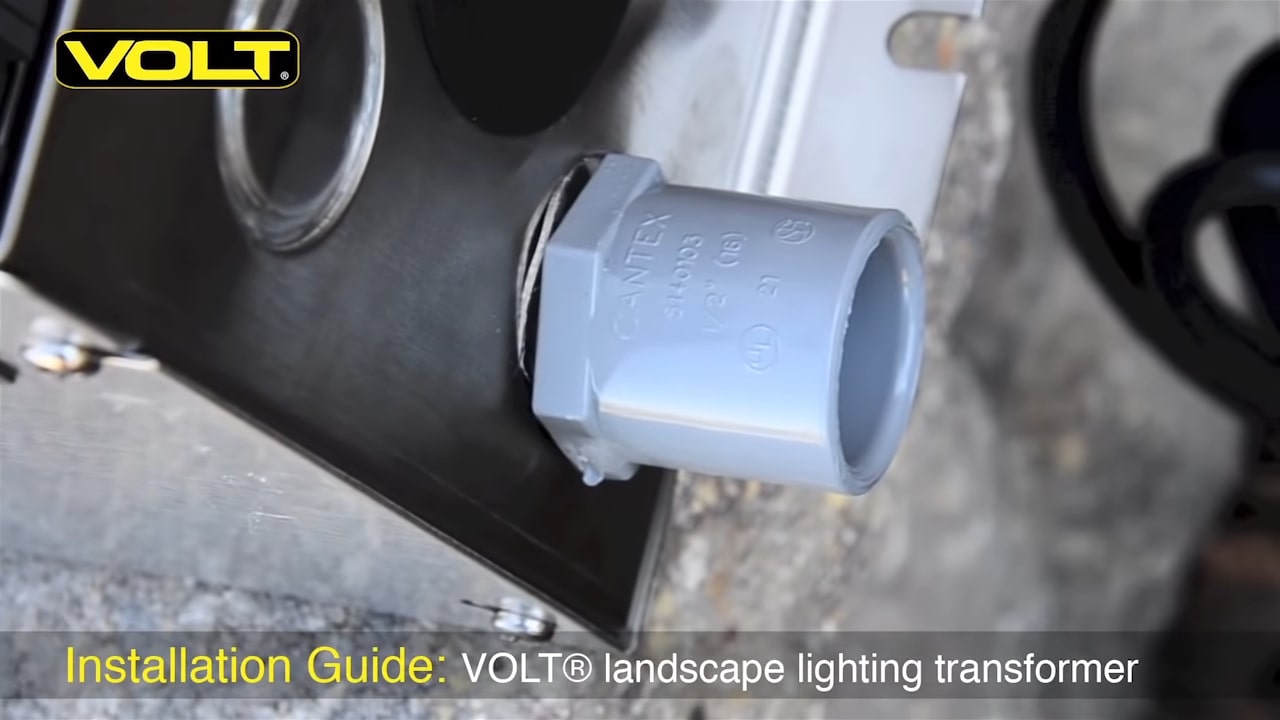
Step 3: With the 0.5-inch knockout removed, install a terminal adapter in the bottom of the transformer. With the half-inch terminal ring clamp screwed down, it makes the terminal adapter fit very tight.

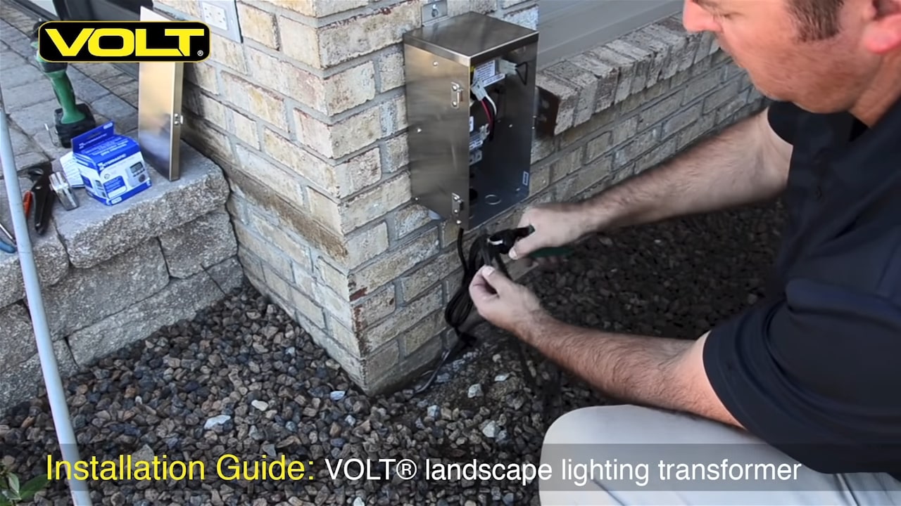
Step 4: Set the transformer in the approximate location where it’s going to be hung. You must maintain at least 12 inches of clearance between the bottom of the transformer and the ground. Use a pencil to mark the top hole. In the top hole that you mark, use a hammer drill and drill a hole about 1 inch deep. Then take a masonry anchor and screw, insert them in the hole and set them in place. Thread in the anchor screw and leave about a 1/8th inch gap so that the transformer can be hung on the screw.

Step 5: With the transformer hanging vertically, mark the bottom hole. Slide the transformer aside and now drill the hole for the bottom anchor sleeve. Put your masonry anchor and screw together, put them in the hole and secure it down with the screwdriver. With the bottom screw in place, you can now secure down the top screw for the transformer.
Step 6: With the transformer in place, measure how much wire will be needed to go up inside the transformer, then cut off the excess.

Step 7: Use a tape measure to measure the length of 0.5-inch PVC conduit needed and cut it with a pipe saw or PVC pipe cutters. Slide the cut conduit over the end of the wire. Now thread the wire up through the bottom of the terminal adapter and twist the pipe up into the socket. Then with the cable and conduit in place, backfill the hole at the bottom of the transformer.
Tip
You’ll now need the following tools to wire the transformer:
- A pair of offset cutters is a great idea for cutting wire.
- An offset flat-head screwdriver; the small bit size fits the screw terminals on the transformer very well.
- Wire strippers; ones with wire size gauges make it easy to identify the correct knife size.
- If running multiple cables, identify each one with a different colored tape; this is a good way to organize your system layout. Label the inside of your transformer cover with the color of each run, description and wattage used.

Step 8: Use wire cutters to separate the two ends of the wire; pull them apart. Use wire strippers to expose about 1 inch of the cable. Loosen the screw clamps on the voltage lugs and twist the wire ends. One of the conductors will always be placed on the common side. Insert it and tighten it down. Then take the other conductor and place it in the other appropriate voltage tap and tighten it down.
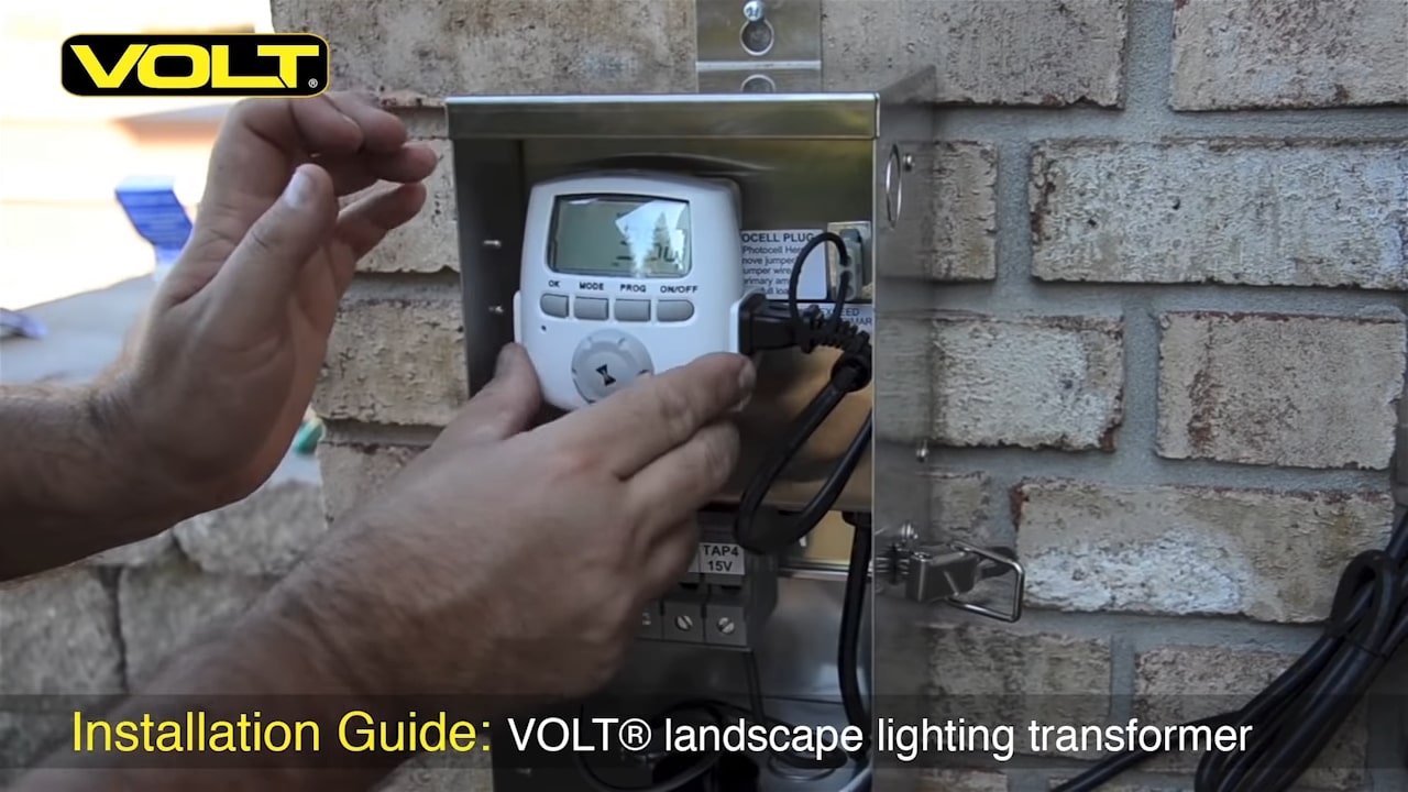
Step 9: Install the control device for your transformer. Remove the terminal plug from the transformer and plug it into the receptacle on the timer. Now plug the timer unit into the receptacle on the transformer.
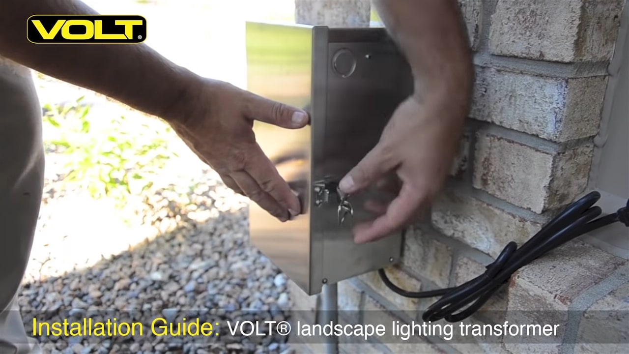
Step 10: Reinstall the transformer door by lining up the pins onto the barrel sockets and sliding it down into place. Close and latch the door, and plug the transformer into a GFI receptacle with a weather-tight box.
Requirements for Transformer Installation
- The transformer must be plugged into a GFCI (ground-fault circuit-interrupter) circuit (either a GFCI receptacle or GFCI breaker at the circuit panel)
- Do not use extension cords with transformers.
- The transformer must be mounted in a vertical position.
- The bottom of the transformer must be at least 12 inches from the ground.
- A transformer may become hot; do not mount on vinyl.
About Transformer Capacity
- On the secondary side (low voltage taps) of the VOLT® 300 Watt (12v-15v) Multi-Tap Low Voltage Transformer, for example, each circuit has its own magnetic circuit breaker (toggle switch) that is connected to a common tap (marked with a “COM” label). These common taps can accommodate up to 300W (25A). When the transformer capacity is less than 300W, the capacity will be equal to the transformer capacity.
- Even though the capacity of each common tap is 300W (or transformer capacity if less than 300W), the National Electrical Code specifies that a circuit can only be loaded up to 80% of its maximum. That means that the working capacity is 240W (or 80% of the transformer capacity is smaller than 300W). Furthermore, it is important to account for the loss of current through the wire, which reduces the capacity by an additional 10%. This means that the true optimal working capacity of a transformer is about 70% of the transformer’s total capacity.
How to Connect Lighting Runs to the Transformer
The home run cable (e.g. 10/2 or 12/2) has two wires. One wire gets connected to the common terminal (labeled “COM”); the other wire connects to a voltage terminal (the colored labels that say 12, 13, 14, etc). Low voltage wire does not have polarity; it does not matter which of the two wires connects to the common terminal and which to the voltage terminal, as long as one wire goes to each.
The correct voltage terminal is the one that results in an optimal voltage at the fixtures connected to that run. For example, with our 300W Multi-Tap Transformer, you can output at a variety of voltages to compensate for voltage drop. So if you have a long run of 100 feet, you may need to use the 15v voltage terminal in order to have 12v of power all the way out at the far away fixtures.
You can hook up multiple home runs to each and any of the terminals. For example, you may have six home runs, in which case you would have six wires in the same COM terminal and the other half of the 10-2 wires go into the voltage terminals, which can have multiple runs/wires in each tap as well.
To connect a home-run wire to the terminals:
- Split the paired wire down the middle to separate the two wires and strip half an inch of insulation off each wire. One end goes to the COM terminal, the other into a voltage terminal.
- Loosen the terminal screws with a small flat head screwdriver and insert the wire into the terminal opening, which is located at the bottom (90 degrees from the terminal screw facing the bottom of the transformer).
- Tighten the screw to secure wire(s).
Tips for a Successful Transformer Installation
- Generally, it is a good practice to connect each of your home run lines directly to the transformer, spreading them evenly among the available commons. Ideally, if two or more home run wires share a voltage tap, then connect them to the same common.
- Optional timers and photocells plug right into the transformer ports labeled and located inside the cabinet.
- It is easier to see and insert the wires into their terminals when the transformer is lying on the ground. Affix all your wires BEFORE mounting the transformer.
How to Troubleshoot a Low Voltage Transformer
- First, check that there is power at the GFI outlet. Do not assume there is power. Check it with a voltmeter and make sure there is 120v AC. If you have a timer, please unplug/remove it. They are often a source of failure.
- Test the timer outlet inside the transformer cabinet with a voltmeter. You should have 120v AC there as well. If you do, go ahead and plug the timer receptable cord or dummy timer back into the timer receptacle outlet to complete the circuit or else the transformer will not operate. Please remove the photocell, if you have one installed.
- If applicable, insert the photocell jumper into the photocell receptacle port to complete the circuit or else the transformer will not operate. Be sure the jumper is pushed down tight. If a photocell is installed, the transformer will not turn when it is light out. Even if you cover the photocell eye there will be a delay. The photocell needs to be covered for several minutes before it will allow the transformer to turn on.
- Make sure all the toggle switches are in the “ON” position (UP). The toggle switches are circuit breakers and can trip if there is a surge, overload or short. Sometimes the circuit breakers themselves can fail.
- Finally, test the secondary side (low voltage taps/multi-tap) of the transformer. Do not use the screws facing forward to test for voltage. Use a voltmeter inside the slot that holds the cable (either underneath the screw terminals or under the clamping levers). Put one voltmeter prong on the common, the other on a tap (12v tap, 13v tap etc..). You should read approximately the same voltage as the tap you’re testing ie. Read 15v if you’re testing the 15v tap. If you do not get any voltage, remove any wires (home run wires) from the common and the voltage taps you are testing and try again without any load.
About VOLT® Transformers
VOLT® low voltage transformers are the best in the landscape lighting industry. All VOLT® transformers are backed by our lifetime warranty and are ETL listed to UL standards. They each feature toroidal cores, weatherproof stainless steel cabinets, timer and photocell receptacles, and magnetic secondary circuit breakers for each 300W common circuit.